Hollow Structural Section

(HSS)

Overview

Bull Moose® maintains extraordinarily high standards in Hollow Structural Steel tube—so that our products stand the test of time. Whether exposed to the elements or hidden behind walls, we know that our HSS components are a key contributor to structural integrity.

Direct-form manufacturing gives our products an advantage right from the start. Direct-form means we can use the highest grade HSLA steel and form it directly into a tube. This minimizes the cold working process, which can change the characteristics of the steel.

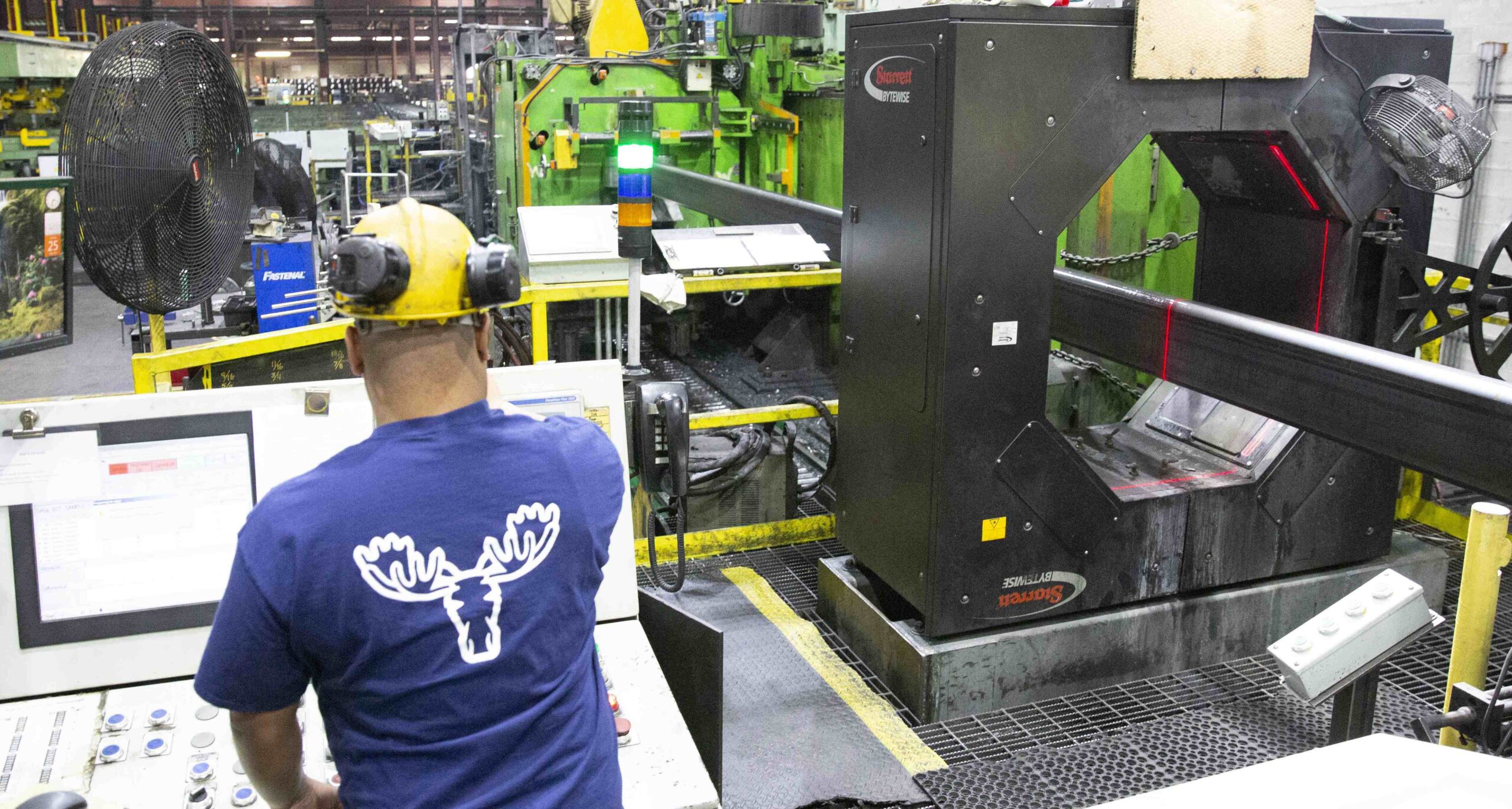
Bull Moose Tube HSS ProductionBull Moose Advantages

  • Wide ranges of yield strengths; 46 KSI to 110 KSI.
  • Tighter tolerances, sharper corners and straighter tubes.
  • Less residual stress on the steel
  • Widest variety of custom sizes and lengths, including metric sizes and cut-to-length options
  • Special packaging

STRATUSTEEL

We’re Taking High-Strength, Lightweight Steel to New Heights

Stratusteel® from Bull Moose® is revolutionary hollow structural steel tubing that’s three times harder than conventional steel, and achieves strength ratings in excess of 100 and 110 KSI…at a weight that’s as much as 35% below other steel.

This robust technology enables cranes to reach higher, trailers to carry more weight, rescue ladders to extend farther — all without compromises in strength.

Bull Moose Tube HSS ProductionAbout The Product

STRONGER: Stratusteel® achieves strength ratings from 100 to 110 KSI, compared the 50 to 80 KSI ratings of conventional steel. Produced in accordance with ASTM A1112, our product is stronger — which means you can load more or extend further.

LIGHTER: Living up to its stratus-cloud namesake, Stratusteel® is as much as 35% lighter than standard steel products.
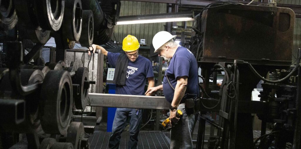
TOUGHER: Stratusteel® is 3x harder than standard steel as measured by the Rockwell hardness scale. As a result, products made of Stratusteel® have an impact-resistant toughness that enables them to take a beating and look newer, longer. This hardness also enables extendable products (such as booms and fire truck ladders) to extend farther without sway or bounce.

CREATES VALUE FOR YOU IN SIGNIFICANT WAYS: For truckers, less weight = more freight. For booms, cranes, and ladders, it’s stronger so you can extend longer. For every application, it performs as some of the toughest, most durable steel ever, prolonging the life and value of heavy-duty equipment.

CURRENT APPLICATIONS: Military vehicles, launch pad scaffolding, ladders, booms, agricultural equipment, heavy haul trailers.

About The Name

We presented several possible product names to hundreds of opinion-leaders in the transportation industry, and let them vote for their favorite. The final selection: Stratusteel®. Named after the steel-gray stratus clouds that can span the horizon, Stratusteel® is just as far-reaching and nearly as light.

WEATHERING GRADE STEEL TUBE

The Low-Cost, No Maintenance Alternative to Outdoor Applications

With the rising cost of galvanized steel, it’s good to know there’s a solid substitute: Weathering Grade steel tube from Bull Moose®.

Compare this stock to COR-TEN® and other ASTM A847 options, and you’ll find that our Weathering Grade steel delivers equivalent performance for heavy weather environments…cost-effectively.

Over time, the surface of this alloy steel develops a stable, light-brown patina that protects it from corrosion—and eliminates the need for painting and re-painting.

Its durability and 50 KSI strength make it ideal for applications such as walkways, bridges, railings, and other structures that are directly exposed to the elements.

Bull Moose Weathering Grade stock is readily available in multiple lengths, shapes, and wall thicknesses to fit an extensive range of projects.

Product Details

  • Produced per ASTM A847, which mirrors ASTM A500 (plus atmospheric-corrosion-resistant steel)
  • 50ksi min. yield, 70ksi min. tensile, 19% min. elongation.
  • General applications: bridges, utility/light poles.
  • Normally in stock:
    • 3/16”
    • 1/4”
    • 3/8″
    • (Custom sizes: inquire on lead time)
  • Uncoated weathering steel typically provides initial cost savings of 10-15% by avoiding the expense of painting, and savings of at least 30% over the life of the structure.
  • The steel’s weathered finish provides a natural look for outdoor environments, and because it is permanent, it does not require either VOC paint or blasting—both of which can be harmful to the environment. 

Relevant Documentation


Document Text:

Stratusteel
Next Generation HSS

We’re taking high-strength, lightweight steel to new heights.

BMT Welding Guide for Stratusteel used in transportation and other heavy equipment industries. In this guide you will find suggestions for using Stratusteel tubing in applications such as transportation and heavy equipment. This is intended to be a general guideline only—please always refer to your tube manufacturer or raw steel provider’s specifications where necessary.

Table of Contents

Introduction 3

  1. Preparation 4
  2. Welding 4
  3. Recommended Welding Materials for Stratusteel  4

Table #1: Recommended weld wire for Stratusteel 4

  1. Preheat and Inter-pass Temperature Considerations 5
  2. Hydrogen Cracking Risks 5

Table #2: Rules of thumb for handling prior to welding 5

  1. Heat Affected Zone (HAZ) or Soft Zones 5
  2. Direction and Passes for Welding 6

Figure #1: Impact of starting welds in joint locations 6

Figure #2: Improved impact of starting welds in parent material 6

7.1. Welding Parameters Analyzed  7

Table #3: Weld parameters used for thermal stress analysis  7

7.2 Real-World Example of Welding Parameters Used in Construction of Trailer Frames  7

Table #4: Weld Parameters used during real-world construction of 8-gauge 3”x5” Stratusteel 7

  1. Fabrication Considerations 8
  2. Final Considerations 8

Stratusteel™ hollow steel tubing from Bull Moose is stronger than steel, and lighter than aluminum configured to bear the same load. As a result, you can reduce the weight of your design by as much as 35% while getting the strength and other benefits  of steel. With Stratusteel, your designs will be dramatically lighter, stronger, and more efficient!

Introduction 

Welding  of Stratusteel will be different than typical A500 50MY – 80MY tubing. Stratusteel is greater  than or equal to 100MY, and as a result, welding requirements are slightly different. When  welded  properly, Stratusteel will ensure long-lasting performance  while making your designs lighter, stronger  and more efficient to manufacture.

1. Preparation 

All well-established methods or processes of preparation can be used with Stratusteel.   However, attention should be paid to any potential buildup of materials on the surface of weld joint, such as thin oxides films from thermal cutting. Make sure all joints are well cleaned prior to welding.  If using a plasma cutting for joint preparation, oxygen should be used to minimize risk of porosity in the weld material during welding. It is also possible to use a grinding method, which would remove the risk of porosity in the weld material. It’s recommended to grind down by at least 0.2mm if using this method post plasma cutting. 

2. Welding  

All common fusion welding methods can be used for welding Stratusteel, such as: 

  • MAG/MIG – Welding 
  • MMA-Welding 
  • TIG-Welding 
  • Plasma Welding 
  • Submerged Arc Welding 
  • Laser Welding 

While other methods can be used, these are the most common for Stratusteel. Of these, MAG/MIG welding is the most commonly used welding technique known today. When T-joint welds are close to the edge with a thickness ≥ 8 mm, there should be no sharp defects at the edge. Such defects can lead to stresses in the thickness direction, which can lead to cracking during welding. These welds should be avoided. Shearing is not expected in the use of Stratusteel due to its shape and size. However, if shearing is used, welding should not occur near the sheared area, as it gives increases in stress at the shear location (which can lead to cracking at the weld location in contact with the shear location). It’s recommended that if the location must be used, that it’s  thermally cut instead of sheared. 

3. Recommended Welding Materials for Stratusteel

Stratusteel should be welded with high strength solid welding wire

MAG-Welding (GMAW) MAG Cored Wire MMW Coated Electrode Submerged Arc Welding
AWS:A5.28 ER100S-X AWS:A5.29 E11XT-X AWS:A5.5 E11018 AWD:A5.23 F11X
AWS:A5.28 ER110S-X EN 18726(-a)T69X EN757 E69X EN 26304(-A) S69X
EN 16834(-A) 69X

Table #1: Recommended weld wire for Stratusteel

4. Preheat and Inter-pass Temperature Considerations 

Multi-pass welding may cause the temperature in the welded joint to rise to a level that causes the strength to drop. This is most critical for welds below 500mm, because the temperature will drop between weld bead formations.  The maximum inter-pass temperature for Stratusteel is  100 degrees C.  For short welds, it is recommended to allow the temperature to cool to 150  degrees C prior to starting the next weld bead. For best results, it is recommended for Stratusteel to be at standard room temperature (temp ≥  23 degrees C ≤100 degrees C) prior to welding. 

5. Hydrogen Cracking Risks 

This risk of hydrogen cracking is very low; however, it can occur under very specific conditions. Hydrogen cracking will occur if European Standard 1011-2 is met, whereby a very high hydrogen content > 15 ml/100g of weld metal material and an extremely low heat input of < 0.5Kj/mm are applied, with a combined thickness of 30mm of Stratusteel.  These conditions are very rare— however, it is critical to monitor and prevent these conditions in order avoid risk of hydrogen cracking during welding.  To avoid this risk, it’s recommend that you use weld materials with low hydrogen content ≤ 10 ml/100g weld metal. When welding Stratusteel it’s important to also follow good general welding practice to avoid increased risk of hydrogen cracking. Rules of thumb to follow to minimize hydrogen cracking are:

Minimize the hydrogen content in and
around the prepared joint.
Minimize the stresses in the weld join.
Use the correct pre-heat and inter pass
temperatures.
Do not use welding consumables of a
higher strength than is necessary.
Use welding consumables with low
hydrogen content.
Arrange the weld sequence so that the
residual stresses are reduced during the
welding process along the weld seem nor
in the welded joints.
Keep impurities out of the weld area. Set the gap in the joint to a maximum of
3mm.

Table #2: Rules of thumb for handling prior to welding


6. Heat Affected Zone (HAZ) or Soft Zones When using Stratusteel, soft zones can form in the HAZ.  This can happen as a result of changes in the microstructure during welding.  However, if normal heat inputs are used, then these soft zones typically do not influence the strength of the weld.  For example, if an inter-pass temperature of 150 degrees C is maintained using a single pass, then the heat input which would affect Stratusteel could be increased by 10 – 15% for a butt weld, and approximately 40 – 50% for a filet weld. Following the inter-pass temperature limits will reduce if not eliminate any impact in HAZ leading to soft zones.

7. Direction and Passes for Welding When using Stratusteel we recommend that you start your weld bead in the larger section of the parent material and then work towards the joint. For two pass welds we recommend that once at the joint, the welder restart from the larger section going into the joint (as opposed to returning from the joint to larger section).  Please see figure #1 as a representation of starting welds at joint locations.

Restarting second pass welds in the larger parent material allows for inter pass cooling and reduction of stresses at the joint.  If welding a plate, it is recommended that the plate use a  notch of at least 1” in radius at the joint to prevent concentration of stresses at the joint an follow the inter pass recommendations above.

7.1. Welding Parameters Analyzed As part of this guide, extensive thermal analysis was performed in order to generate stress analysis curves and impact of welding conditions.  Below is the table of welding parameters used  for this section: 

Material: ¼ wall Stratusteel
Weld Type: MIG – Non-Pulsed
Voltage: 23-25V
Amperage: 300-360A
Weld Speed: 24-26 in/min
Preheat: N/A (25 C)
Weld Size: 3/16” fillet +/-.03125

Table #3: Weld parameters used for thermal stress analysis

7.2 Real-World Example of Welding Parameters Used in Construction of Trailer Frames Below is a table of real-world welding parameters which yielded the best results for the gauge of  tubing applied:

Material: 8-gauge 3”x5” Stratusteel
Weld Type: MIG – Non-Pulsed
Voltage: 28V
Amperage: 245A
Weld Wire Speed: 420 ipm
(i.e., welder speed should still be as above)
Weld Wire Size: .035 weld wire

Table #4: Weld Parameters used during real-world construction of 8-gauge 3”x5” Stratusteel

8.    Fabrication Considerations When fabricating (welding) Stratusteel HSS, consideration should be taken to reduce the residual stresses imparted into the HSS from the shop/field welding process. The weld seam on the HSS should be oriented, if possible, where thermal stresses will not affect the weld seam. For example, orienting the HSS weld seam in a restrained position under a reinforcement plate, bracket, etc., to minimize buildup of residual stresses. Cutouts and holes, where possible,  should be placed away from or opposite the weld seam face.

9.    Final Considerations All steps mentioned above should be taken when welding Stratusteel.  In addition, you should make every effort to have a clean, moisture-free weld area for best results.  Condensation, dirt,  and any other foreign material should be removed prior to welding.  Always monitor and prevent conditions that could cause hydrogen cracking. Please feel free to contact us at Bull Moose Tube Technical Support with any questions or concerns. Bull Moose maintains an unwavering commitment to quality, precision, and technical expertise. For reliable technical support, or capable collaboration with product development, please call  888.227.5430, or email techsupport@bullmoosetube.com.

Document Text: 

Depend on the strength and reliability of Bull Moose when it comes to hollow Structural Steel Tube.

Our products stand the test of time. Whether exposed to the elements or hidden behind walls, we know that your structure and tenants are counting on us. You need reliable service and products of exceptional strength. You need Bull Moose.

Direct-form manufacturing makes us unique. Direct-form means we can use the highest grade HSLA steel, which is directly formed into a tube. This minimizes the cold-working process, which can change the characteristics of the steel.

BULL MOOSE ADVANTAGES: 

  • Tubes with strength ranges of 46 KSI to 110 KSI 
  • Tighter tolerances, sharper edges and straighter tubes 
  • Widest variety of custom sizes and lengths, including metric sizes and cut-to- length options

OTHER BENEFITS/SERVICES:

  • Specialized packaging
  • Leading availability and fastest delivery due through 8 North American sites
  • Readily available weathering grade steel
  • Readily available Charpy V-Notch steel
  • In-line NDT weld testing available on all tube

Leading the Herd

Founded in 1962, Bull Moose Tube has been delivering products of formidable quality for more than half a century. With sizes ranging from 1-1/2” square through 18” x 6” rectangle, and wall thicknesses of 1/8” through 5/8” Bull Moose features one of the largest size ranges of HSS products in the industry.

And with eight North American manufacturing and warehouse facilities, Bull Moose has the HSS products you need when you need them.

You need strength and reliability. You need availability.

You need Bull Moose Tube.

EIGHT WORLD-CLASS LOCATIONS DELIVERING BEST-IN-CLASS PRODUCTS


Document Text: 

Stratusteel

110 KSI Steel Tube

It’s Might… Made Light™.

The Strongest, Lightest Steel Tubes on the Planet

LIGHTWEIGHT STEEL WITH HEAVYWEIGHT PERFORMANCE

Stratusteel®  is a revolutionary hollow structural steel tubing that delivers an extraordinary set of characteristics:

High Strength = Yield strengths as high as 110KSI, enabling your products to support greater loads and span greater distances.

Light Weight = 35% lighter than an equivalent A500 50KSI product!

2x Harder than Steel = Your products become more durable and sustainable; remain better-looking, longer.

CUSTOM SIZES AND PROFILES

Stratusteel is available in a broad range of standard and metric sizes. But our variable tooling mills also allow for custom tube profiles. We can optimize wall thickness and outer dimensions/contours for your specific needs.

Customizing for your exact application saves you from buying bulkier stock than you really need…making Stratusteel a high value custom product for a standard steel price!

Here’s an example:

Your design shows that a 3.83” x 5.75” x 0.197” HSS will work on your product (weighing 11.98 lbs/ft.).

If the nearest size in conventional HSS is 4” x 6” x .025” (weighing 15.62 lbs/ft.), you’ll experience an unnecessary 23% increase in weight and thus a 23% increase in cost!

Stratusteel would enable you to avoid those increases with efficient, optimal dimensions and weight.

HOW DOES STRATUSTEEL BENEFIT YOU? 

ENGINEERS: Explore new design options with lighter, more streamlined products. Switching to Stratusteel

from ASTM A500 Grade B can enable a wall thickness reduction of 35%. It may even enable you to reduce the number of steel components in your assembled product.

PURCHASING AGENTS: Every pound of steel you don’t have to buy is a direct savings for your bottom line.

SHIPPERS: Smaller, lighter products mean fuller shipments and lower shipping costs. This enables you to

get the most out of every freight mile—ultimately reduces demands on drivers’ time, and fuel consumption.

MARKETERS: With Stratusteel, your product may potentially be positioned as the lightest, strongest of its kind on the market.

Finishes available:

  • Post-pickled in oil
  • EPS (Eco-Pickled Surface)

Stratusteel

Contact us to explore the advantages Stratusteel can bring your product line!

HSS STRATUSTEEL®–100 SECTION PROPERTIES / SQUARES & RECTANGLES

Nominal Size Weight per ft Design Wall Thick. X-X Axis Y-Y Axis Torsional Stiffness Constant Torsional Shear Constant Surface Area
Depth Width Wall t b/t h/t area lx Sx rx Zx ly Sy ry zy j h /ft.
in. in. in ga. in lb. in. ft.2 in.4 in.3 in. in.3 in.4 in.3 in. in.3 in.4 in.3 ft.2
3 1.5 - 14 0.083 2.39 0.077 16.5 36.0 0.65 0.756 0.504 1.07 0.627 0.257 0.343 0.627 0.387 0.624 0.639 0.73
3 1.5 - 12 0.109 3.07 0.101 11.9 26.7 0.84 0.948 0.632 1.06 0.796 0.320 0.426 0.616 0.490 0.789 0.815 0.72
3 1.5 - 11 0.120 3.35 0.112 10.4 23.8 0.93 1.03 0.686 1.05 0.869 0.346 0.461 0.611 0.534 0.861 0.892 0.72
2 2 - 14 0.083 2.11 0.077 23.0 23.0 0.58 0.351 0.351 0.780 0.412 0.351 0.351 0.780 0.412 0.559 0.568 0.64
2 2 - 12 0.109 2.70 0.101 16.8 16.8 0.74 0.437 0.437 0.768 0.521 0.437 0.437 0.768 0.521 0.708 0.724 0.64
2 2 - 11 0.120 2.94 0.112 14.9 14.9 0.81 0.437 0.473 0.763 0.568 0.473 0.473 0.763 0.568 0.773 0.793 0.63
2 2 - 10 0.134 3.25 0.125 13.0 13.0 0.90 0.513 0.513 0.756 0.621 0.513 0.513 0.756 0.621 0.846 0.871 0.63
2 2 - 8 0.165 3.88 0.165 9.12 9.12 1.14 0.62 0.62 0.737 0.768 0.62 0.62 0.737 0.768 1.05 1.09 0.619
4 2 - 14 0.083 3.24 0.077 23.0 48.9 0.89 1.86 0.928 1.45 1.14 0.636 0.636 0.848 0.708 1.52 1.16 0.98
4 2 - 12 0.109 4.19 0.101 16.8 36.6 1.14 2.35 1.18 1.43 1.46 0.802 0.802 0.837 0.905 1.94 1.49 0.97
4 2 - 11 0.120 4.58 0.112 14.9 32.7 1.26 2.57 1.29 1.43 1.61 0.873 0.873 0.832 0.991 2.13 1.64 0.97
4 2 - 10 0.134 5.07 0.125 13.0 29.0 1.40 2.82 1.41 1.42 1.77 0.954 0.954 0.826 1.09 2.34 1.81 0.96
4 2 - 8 0.165 6.13 0.165 9.12 21.2 1.8 3.52 1.76 1.4 2.24 1.18 1.18 0.81 1.37 2.95 2.3 0.953
4 2 3/16 0.1875 0.1875 6.87 0.188 7.64 18.3 2.02 3.88 1.94 1.39 2.49 1.29 1.29 0.799 1.52 3.27 2.57 0.946
3 3 - 14 0.083 3.24 0.077 36.0 36.0 0.89 1.25 0.833 1.19 0.964 1.25 0.833 1.19 0.964 1.95 1.31 0.98
3 3 - 12 0.109 4.19 0.101 26.7 26.7 1.14 1.58 1.06 1.18 1.23 1.58 1.06 1.18 1.23 2.51 1.69 0.97
3 3 - 11 0.120 4.58 0.112 23.8 23.8 1.26 1.73 1.15 1.17 1.35 1.73 1.15 1.17 1.35 2.75 1.86 0.97
3 3 - 10 0.134 5.07 0.125 21.0 21.0 1.40 1.90 1.26 1.16 1.49 1.90 1.26 1.16 1.49 3.03 2.06 0.96
3 3 - 8 0.165 6.13 0.165 15.2 15.2 1.8 2.36 1.57 1.15 1.89 2.36 1.57 1.15 1.89 3.89 2.36 0.953
3 3 3/16 0.1815 0.1875 6.87 0.188 13 13 2.02 2.61 1.74 1.14 21 2.61 1.74 1.14 2.1 4.29 2.95 0.946

HSS STRATUSTEEL®–100 SECTION PROPERTIES / SQUARES & RECTANGLES

Nominal Size Weight per ft Design Wall Thick. X-X Axis Y-Y Axis Torsional Stiffness Constant Torsional Shear Constant Surface Area
Depth Width Wall t b/t h/t area lx Sx rx Zx ly Sy ry zy j h /ft.
in. in. in ga. in lb. in. ft.2 in.4 in.3 in. in.3 in.4 in.3 in. in.3 in.4 in.3 ft.2
4 3 - 14 0.083 3.80 0.077 36.0 48.9 1.04 2.45 1.22 1.53 1.45 1.58 1.05 1.23 1.19 3.00 1.76 1.14
4 3 - 12 0.109 4.93 0.101 26.7 36.6 1.35 3.12 1.56 1.52 1.86 2.01 1.34 1.22 1.53 3.86 2.28 1.14
4 3 - 11 0.120 5.39 0.112 23.8 32.7 1.49 3.42 1.71 1.52 2.04 2.20 1.47 1.22 1.68 4.24 2.51 1.13
4 3 - 10 0.134 5.98 0.125 21.0 29.0 1.65 3.76 1.88 1.51 2.25 2.41 1.61 1.21 1.85 4.68 2.78 1.13
4 3 - 8 0.160 7.05 0.149 17.1 23.8 1.94 4.35 2.18 1.50 2.63 2.79 1.86 1.20 2.16 5.47 3.26 1.12
4 3 3/16 0.1875 0.1875 8.15 0.188 13 18.3 2.4 5.24 2.62 1.48 3.21 3.35 2.23 1.18 2.63 6.68 4 1.11
6 3 - 14 0.083 4.93 0.077 36.0 74.9 1.35 6.48 2.16 2.19 2.64 2.24 1.49 1.29 1.64 5.27 2.66 1.48
6 3 - 12 0.109 6.41 0.101 26.7 56.4 1.75 8.32 2.77 2.18 3.41 2.86 1.91 1.28 2.11 6.80 3.45 1.47
6 3 - 11 0.120 7.03 0.112 23.8 50.6 1.93 9.14 3.05 2.17 3.75 3.13 2.09 1.27 2.32 7.48 3.80 1.46
6 3 - 10 0.134 7.81 0.125 21.0 45.0 2.15 10.1 3.36 2.17 4.15 3.45 2.30 1.27 2.57 8.27 4.22 1.46
6 3 - 8 0.160 9.23 0.149 17.01 37.3 2.54 11.8 3.92 2.15 4.87 4.00 2.67 1.26 3.01 9.69 4.96 1.45
6 3 3/16 0.1875 0.1875 10.7 0.188 13 28.9 3.15 14.3 4.77 2.13 5.98 4.84 3.23 1.24 3.69 11.9 6.12 1.80
8 3 - 12 0.109 7.89 0.101 26.7 76.2 2.15 17.0 4.25 2.81 5.36 3.71 2.47 1.31 2.70 9.91 4.62 1.80
8 3 - 11 .120 8.66 0.112 23.8 68.4 2.38 18.7 4.68 2.80 5.91 4.07 2.71 1.31 2.97 10.9 5.10 1.80
8 3 - 10 0.134 9.63 0.125 21.0 61.0 2.65 20.7 5.17 2.80 6.55 4.48 2.99 1.30 3.29 12.1 5.65 1.79
8 3 - 8 0.160 11.41 0.149 17.1 50.7 3.13 24.2 6.06 2.78 7.70 5.21 3.48 1.29 3.86 14.2 6.66 1.78
8 3 3/16 0.1875 0.1875 13.25 0.188 13 39.6 3.9 29.7 7.43 2.76 9.51 6.33 4.22 1.27 4.74 17.4 8.23 2.14
10 3 - 12 0.109 9.38 0.101 26.7 96.0 2.56 30.0 6.01 3.43 7.72 4.56 3.04 1.33 3.28 13.1 5.79 2.13
10 3 - 11 0.120 10.29 0.112 23.8 86.3 2.83 33.1 6.61 3.42 8.51 5.00 3.33 1.33 3.62 14.4 6.39 2.13
10 3 - 10 0.134 11.45 0.125 21.0 77.0 3.15 36.6 7.32 3.41 9.44 5.51 3.68 1.32 4.01 16.0 7.09 2.13
10 3 - 8 0.160 13.58 0.149 17.1 64.1 3.73 43.0 8.59 3.39 11.1 6.43 4.28 1.31 4.71 18.7 8.36 2.21


HSS STRATUSTEEL®–100 SECTION PROPERTIES / SQUARES & RECTANGLES

Nominal Size Weight per ft Design Wall Thick. X-X Axis Y-Y Axis Torsional Stiffness Constant Torsional Shear Constant Surface Area
Depth Width Wall t b/t h/t area lx Sx rx Zx ly Sy ry zy j h /ft.
in. in. in ga. in lb. in. ft.2 in.4 in.3 in. in.3 in.4 in.3 in. in.3 in.4 in.3 ft.2
10 3 3/16 0.1875 0.1875 15.8 0.188 13 50.2 4.66 52.8 10.6 3.37 13.8 7.82 5.21 1.3 5.8 23 10.3 2.11
9 1/2 3 1/2 - 12 0.109 9.38 0.101 31.7 91.1 2/56 28.6 6.01 3.34 7.56 6.07 3.47 1.54 3.77 16.3 6.45 2.14
9 1/2 3 1/2 - 11 0.120 10.29 0.112 28.3 81.8 2.83 31.5 6.62 3.33 8.35 6.67 3.81 1.54 4.15 17.9 7.12 2.13
9 1/2 3 1/2 - 10 0.134 11.45 0.125 25.0 73.0 3.15 34.8 7.33 3.33 9.26 7.36 4.21 1.53 4.60 19.8 7.90 2.13
9 1/2 3 1/2 - 8 0.160 13.48 0.149 20.5 60.8 3.73 40.9 8.61 3.31 10.9 8.60 4.91 1.52 5.41 23.3 9.33 2.12
9 1/2 3 1/2 3/16 0.1875 0.191 16.08 0.178 16.7 50.4 4.42 47.9 10.1 3.29 12.9 10 5.73 1.51 6.36 27.4 11 2.12
10 3 1/2 - 12 0.109 9.75 0.101 31.7 96.0 2.66 32.5 6.50 3.50 8.22 6.36 3.63 1.55 3.94 17.3 6.79 2.22
10 3 1/2 - 11 0.120 10.70 0.112 28.3 86.3 2.94 35.8 7.16 3.49 9.07 6.99 3.99 1.54 4.34 19.1 7.50 2.22
10 3 1/2 - 10 0.134 11.91 0.125 25.0 77.0 3.27 39.6 7.93 3.48 10.1 7.72 4.41 1.54 4.81 21.2 8.32 2.21
10 3 1/2 - 8 0.160 14.13 0.149 20.5 64.1 3.88 46.6 9.31 3.47 11.9 9.02 5.15 1.53 5.66 24.9 9.82 2.21
10 3 1/2 3/16 0.1875 0.1875 16.44 0.188 15.6 50.2 4.84 57.4 11.5 3.44 14.7 11 6.29 1.15 6.99 30.7 12.2 2.20
4 4 - 14 0.083 4.36 0.077 48.9 48.9 1.19 3.04 1.52 1.60 1.75 3.04 1.52 1.60 1.75 4.70 2.37 1.31
4 4 - 12 0.109 5.67 0.101 36.6 36.6 1.55 3.89 1.95 1.58 2.25 3.89 1.95 1.58 2.25 6.07 3.07 1.30
4 4 - 11 0.120 6.21 0.112 32.7 32.7 1.71 4.27 2.13 1.58 2.48 4.27 2.13 1.58 2.48 6.69 3.38 1.30
4 4 - 10 0.134 6.89 0.125 29.0 29.0 1.90 4.70 2.35 1.57 2.74 4.70 2.35 1.57 2.74 7.40 3.75 1.30
4 4 - 8 0.160 8.14 0.149 23.8 23.8 2.24 5.46 2.73 1.56 3.20 5.46 2.73 1.56 3.20 8.68 4.41 1.29
4 4 3/16 0.1875 0.1875 9.42 0.188 18.3 18.3 2.78 6.61 3.31 1.54 3.92 6.61 3.31 1.54 3.92 10.7 5.44 1.28
4 4 1/4 0.25 0.25 12.21 0.25 13 13 3.59 8.22 4.11 1.51 4.97 8.22 4.11 1.51 4.97 13.5 6.97 1.26
4 4 5/16 0.3125 0.3125 14.83 0.313 9.78 9.78 4.36 9.59 4.8 1.48 5.91 9.59 4.8 1.48 5.91 16.1 8.39 1.24
6 4 - 14 0.083 5.49 0.077 48.9 74.9 1.50 7.83 2.61 2.28 3.09 4.23 2.11 1.68 2.35 8.52 3.58 1.64


HSS STRATUSTEEL®–100 SECTION PROPERTIES / SQUARES & RECTANGLES

Nominal Size Weight per ft Design Wall Thick. X-X Axis Y-Y Axis Torsional Stiffness Constant Torsional Shear Constant Surface Area
Depth Width Wall t b/t h/t area lx Sx rx Zx ly Sy ry zy j h /ft.
in. in. in ga. in lb. in. ft.2 in.4 in.3 in. in.3 in.4 in.3 in. in.3 in.4 in.3 ft.2
6 4 - 12 0.109 7.15 0.101 36.6 56.4 1.95 10.1 3.36 2.27 4.00 5.43 2.71 1.67 3.04 11.0 4.64 1.64
6 4 - 11 0.120 7.84 0.112 32.7 50.6 2.16 11.1 3.69 2.27 4.41 5.96 2.98 1.66 3.35 12.2 5.12 1.63
6 4 - 10 0.134 8.72 0.125 29.0 45.0 2.40 12.2 4.08 2.26 4.88 6.57 3.29 1.66 3.71 13.5 5.68 1.63
6 4 - 8 0.160 10.32 0.146 23.8 37.3 2.83 14.3 4.77 2.25 5.74 7.67 3.84 1.65 4.35 15.8 6.70 1.62
6 4 3/16 0.1875 0.1875 11.97 0.188 18.3 28.9 3.53 17.5 5.83 2.23 7.07 9.34 4.67 1.63 5.36 19.6 8.3 1.61
6 4 1/4 0.25 0.25 15.62 0.25 13 21 4.59 22.1 7.37 2.19 9.06 11.7 5.85 1.6 6.84 25 10.7 1.6
6 4 5/16 0.3125 0.3125 19.08 0.313 9.78 16.2 5.62 26.2 8.73 2.16 10.9 13.9 6.95 1.57 8.22 30.1 13 1.58
6 4 3/8 - 0.381 22.68 0.354 8.3 13.9 6.26 28.6 9.52 2.14 12.0 15.1 7.53 1.55 9.04 33.2 14.4 1.57
8 4 - 12 0.109 8.64 0.101 36.6 76.2 2.36 20.2 5.04 2.93 6.16 6.96 3.48 1.72 3.83 16.4 6.22 1.97
8 4 - 11 0.120 9.48 0.112 32.7 68.4 2.61 22.2 5.55 2.92 6.79 7.65 3.83 1.71 4.22 18.1 6.86 1.97
8 4 - 10 0.134 10.54 0.125 29.0 61.0 2.90 24.6 6.14 2.91 7.53 8.45 4.23 1.71 4.67 20.0 7.62 1.96
8 4 - 8 0.160 12.49 0.149 23.8 50.7 3.43 28.8 7.20 2.90 8.87 9.88 4.94 1.70 5.50 23.6 9.00 1.96
8 4 3/16 0.1875 0.1875 14.53 0.188 18.3 39.6 4.28 35.4 8.85 2.88 11 12.1 6.05 1.68 6.79 29.2 11.2 1.95
8 4 1/4 0.25 0.25 19.02 0.25 13 29 5.59 45.1 11.3 2.84 14.1 15.3 7.65 1.65 8.72 37.5 14.5 1.93
8 4 5/16 0.3125 0.3125 23.34 0.313 9.78 22.6 6.78 54 13.5 2.8 17.1 18.1 9.05 1.62 10.5 45.2 17.6 1.91
8 4 3/8 0.375 0.375 27.48 0.375 7.67 18.3 8.08 61.9 15.5 2.77 19.9 20.6 10.3 1.6 12.2 52.2 20.5 1.89
10 4 - 12 0.109 10.12 0.101 36.6 96.0 2.76 35.0 7.00 3.56 8.72 8.50 4.25 1.75 4.61 22.0 7.79 2.30
10 4 - 11 0.120 11.11 0.112 32.7 86.3 3.05 38.5 7.71 3.55 9.62 9.35 4.67 1.75 5.09 24.3 8.61 2.30
10 4 - 10 0.134 12.37 0.125 29.0 77.0 3.40 42.7 8.54 3.54 10.7 10.3 5.16 1.74 5.64 26.9 9.56 2.30
10 4 - 8 0.160 14.67 0.149 23.8 64.1 4.03 50.2 10.0 3.53 12.6 12.1 6.05 1.73 6.65 31.7 11.3 2.29
10 4 3/16 0.1875 0.1875 17.08 0.188 18.3 50.2 5.03 61.9 12.4 3.51 15.6 14.8 7.4 1.72 8.22 39.2 14 2.28

HSS STRATUSTEEL®–100 SECTION PROPERTIES / SQUARES & RECTANGLES

Nominal Size Weight per ft Design Wall Thick. X-X Axis Y-Y Axis Torsional Stiffness Constant Torsional Shear Constant Surface Area
Depth Width Wall t b/t h/t area lx Sx rx Zx ly Sy ry zy j h /ft.
in. in. in ga. in lb. in. ft.2 in.4 in.3 in. in.3 in.4 in.3 in. in.3 in.4 in.3 ft.2
10 4 1/4 0.25 0.25 22.42 0.25 13 37 6.59 79.3 15.9 3.47 20.2 18.8 9.4 1.69 10.6 50.4 18.2 2.26
10 4 5/16 0.3125 0.3125 27.59 0.313 9.78 28.9 8.12 95.6 19.1 3.43 24.6 22.4 11.2 1.66 12.8 60.9 22.2 2.24
10 4 3/8 0.375 0.375 37.69 0.375 13 23.7 11.1 145 29 3.61 35.9 65.4 21.8 2.43 25.2 147 40.4 2.56
12 4 - 12 0.109 11.60 0.101 36.6 115.8 3.16 55.3 9.22 4.18 11.7 10.0 5.02 1.78 5.40 27.7 9.37 2.64
12 4 - 11 0.120 12.74 0.112 32.7 104.1 3.50 61.0 10.2 4.17 12.9 11.0 5.52 1.78 5.96 30.6 10.3 2.63
12 4 - 10 0.134 14.19  0.125 29.0 93.0 3.90 67.6 11.3 4.17 14.3 12.2 6.10 1.77 6.61 33.9 11.5 2.63
12 4 - 8 0.160 16.85 0.149 23.8 77.5 4.62 79.6 13.3 4.15 16.9 14.3 7.15 1.76 7.79 39.9 13.6 2.62
12 4 3/16 0.1875 0.1875 19.63 0.188 18.3 60.8 5.78 98.4 16.4 4.13 21  17.5 8.75 1.74 9.66 49.4 16.9 2.62
12 4 1/4 0.25 0.25 25.82 0.25 13 45 7.59 127 21.2 4.09 27.3 22.3 11.2 1.71 12.5 63.6 22 2.6
12 4 5/16 0.3125 0.3125 31.84 0.313 9.78 35.3 9.37 153 25.5 4.04 33.4 26.7 13.4 1.69 15.1 77 26.9 2.58
12 4 3/8 0.375 0.375 37.69 0.375 7.67 29 11.1 178 29.7 4 39 30.5 15.3 1.66 17.6 89 31.4 2.56
4 1/2 4 1/2 - 12 11 0.109 6.41 0.101 41.6 1.75 5.60 2.49 1.79 2.87 5.60 2.49 1.79 2.87 8.71 3.90 1.47
4 1/2 4 1/2 - 11 0.120 7.03 0.112 37.2 37.2 1.93 6.15 2.73 1.78 3.16 6.15 2.73 1.78 3.16 9.60 4.31 1.47
4 1/2 4 1/2 - 10 0.134 7.81 0.125 33.0 33.0 2.15 6.78 3.02 1.78 3.50 6.78 3.02 1.78 3.50 10.6 4.78 1.46
4 1/2 4 1/2 - 8 0.160 9.23 0.149 27.2 27.2 2.54 7.91 3.52 1.77 4.11 7.91 3.52 1.77 4.11 12.5 5.63 1.46
4 1/2 4 1/2 3/16 0.1875 0.1875 10.7 0.188 20.9 20.9 3.15 9.62 4.28 1.75 5.05 9.62 4.28 1.75 5.05 15.4 6.97 1.45
5 5 - 14 0.083 5.49 0.077 61.9 61.9 1.50 6.03 2.41 2.00 2.76 6.03 2.41 2.00 2.76 9.27 3.73 1.64
5 5 - 12 0.109 7.15 0.101 46.5 46.5 1.95 7.76 3.10 1.99 3.57 7.76 3.10 1.99 3.57 12.0 4.84 1.64
5 5 - 11 0.120 7.84 0.112 41.6 41.6 2.16 8.53 3.41 1.99 3.93 8.53 3.41 1.99 3.93 13.2 5.35 1.63
5 5 - 10 0.134 8.72 0.125 37.0 37.0 2.40 9.41  3.77 1.98 4.36 9.41 3.77 1.98 4.36 14.7 5.93 1.63

HSS STRATUSTEEL®–100 SECTION PROPERTIES / SQUARES & RECTANGLES

Nominal Size Weight per ft Design Wall Thick. X-X Axis Y-Y Axis Torsional Stiffness Constant Torsional Shear Constant Surface Area
Depth Width Wall t b/t h/t area lx Sx rx Zx ly Sy ry zy j h /ft.
in. in. in ga. in lb. in. ft.2 in.4 in.3 in. in.3 in.4 in.3 in. in.3 in.4 in.3 ft.2
5 5 - 8 0.160 10.32 0.149 30.6 30.6 2.83 11.0 4.40 1.97 5.12 11.0 4.40 1.97 5.12 17.3 7.00 1.62
5 5 3/16 0.1875 0.1875 11.97 0.188 23.6 23.6 3.53 13.4 5.36 1.95 6.31 13.4 5.36 1.95 6.31 21.4 8.68 1.61
5 5 1/4 0.25 0.25 15.62 0.25 17 127 4.59 16.9 6.76 1.92 8.07 16.9 6.76 1.92 8.07 27.4 11.2 1.6
5 5 5/16 0.3125 0.3125 19.08 0.313 13 13 5.62 20.1 8.04 1.89 9.71 20.1 8.04 1.89 9.71 33.1 13.6 1.58
5 5 3/8 0.375 0.375 22.37 0.375 10.3 10.3 6.58 22.8 9.12 1.86 11.2 22.8 9.12 1.86 11.2 38.2 15.8 1.56
9 5 - 12 0.109 10.12 0.101 46.5 86.1 2.76 30.9 6.87 3.35 8.29 12.6 5.04 2.14 5.55 28.1 8.80 2.30
9 5 - 11 0.120 11.11 0.112 41.6 77.4 3.05 34.1 7.58 3.34 9.15 13.9 5.55 2.13 6.12 31.0 9.73 2.30
9 5 - 10 0.134 12.37 0.125 37.0 69.0 3.40 37.8 8.39 3.33 10.2 15.4 6.14 2.13 6.79 34.4 10.8 2.30
9 5 - 8 0.160 14.67 0.149 30.6 57.4 4.03 44.4 9.87 3.32 12.0 18.0 7.21 2.12 8.01 40.6 12.8 2.29
9 5 3/16 0.1875 0.1875 17.08 0.188 23.6 44.9 5.03 54.8 12.2 3.3 14.9 22.1 8.84 2.1 9.93 50.4 15.9 2.28
9 5 1/4 0.25 0.25 22.42 0.25 17 33 6.59 70.3 15.6 3.27 19.3 28.2 11.3 2.07 12.8 65.2 20.7 2.26
9 5 5/16 0.3125 0.3125 27.59 0.313 13 25.8 8.12 84.7 18.8 3.23 23.4 33.9 13.6 2.04 15.6 79.3 25.4 2.24
9 5 3/8 0.375 0.375 32.58 0.375 10.3 21 9.58 97.8 21.7 3.2 27.3 38.9 15.6 2.02 18.1 92.2 29.7 2.23
6 6 - 12 0.109 8.64 0.101 56.4 56.4 2.36 13.6 4.53 2.40 5.19 13.6 4.53 2.40 5.19 20.9 7.03 1.97
6 6 - 11 0.120 9.48 0.112 50.6 50.6 2.61 15.0 4.99 2.40 5.73 15.0 4.99 2.40 5.73 23.1 7.76 1.97
6 6 - 10 0.134 10.54 0.125 45.0 45.0 2.90 16.5 5.52 2.39 6.35 16.5 5.52 2.39 6.35 25.7 8.62 1.96
6 6 - 8 0.160 12.49 0.149 37.3 37.3 3.43 19.4 6.47 2.38 7.48 19.4 6.47 2.38 7.48 30.3 10.2 1.96
6 6 3/16 0.1875 0.1875 14.78 0.188 28.9 28.9 4.28 23.8 7.93 2.36 9.26 23.8 7.93 2.36 9.26 37.5 12.7 1.95
6 6 1/4 0.25 0.25 19.02 0.25 21 21 5.59 30.3 10.1 2.33 11.9 30.3 10.1 2.33 11.9 48.5 16.5 1.93
6 6 5/16 0.3125 0.3125 23.34 0.313 16.2 16.2 6.87 36.3 12.1 2.3 14.5 36.3 12.1 2.3 14.5 59 20.1 1.91
6 6 3/8 0.375 0.375 27.48 0.375 13 13 8.08 41.6 13.9 2.27 16.8 41.6 13.9 2.27 16.8 68.5 23.5 1.89

HSS STRATUSTEEL®–100 SECTION PROPERTIES / SQUARES & RECTANGLES

Nominal Size Weight per ft Design Wall Thick. X-X Axis Y-Y Axis Torsional Stiffness Constant Torsional Shear Constant Surface Area
Depth Width Wall t b/t h/t area lx Sx rx Zx ly Sy ry zy j h /ft.
in. in. in ga. in lb. in. ft.2 in.4 in.3 in. in.3 in.4 in.3 in. in.3 in.4 in.3 ft.2
8 6 - 12 0.109 10.12 0.101 56.4 76.2 2.76 26.5 6.62 3.10 7.75 17.1 5.70 2.49 6.39 32.1 9.41 2.30
8 6 - 11 0.120 11.11 0.112 50.6 68.4 3.05 29.2 7.29 3.09 8.56 18.8 6.28 2.48 7.05 35.4 10.4 2.30
8 6 - 10 0.134 12.37 0.125 45.0 61.0 3.40 32.3 8.08 3.08 9.50 20.9 6.95 2.48 7.82 39.3 11.6 2.30
8 6 - 8 0.160 14.67 0.149 37.3 50.7 4.03 38.0 9.50 3.07 11.2 24.5 8.17 2.47 9.23 46.5 13.7 2.29
8 6 3/16 0.1875 0.1875 17.08 0.188 28.9 39.6 5.03 46.9 11.7 3.05 13.9 30.2 10.1 2.45 11.4 57.7 17 2.28
8 6 1/4 0.25 0.25 22.42 0.25 21 29 6.59 60.1 15 3.02 18 38.6 12.9 2.42 14.8 74.9 22.2 2.26
8 6 5/16 0.3125 0.3125 27.59 0.313 16.2 22.6 8.12 72.5 18.1 2.99 22 46.5 15.5 2.39 18 91.4 27.2 2.24
8 6 3/8 0.375 0.375 32.58 0.375 13 18.3 9.58 83.7 20.9 2.96 25.6 53.5 17.8 2.36 21 107 32 2.23

A500 / SQUARES

OD1 OD2 Weight per Foot (Pounds)
0.065 0.083 0.095 0.100 0.109 0.120 0.125 0.134 0.188 0.250 0.313 0.375 0.500 0.625 0.750
1 1 0.790 0.976 1.091 1.137 1.218 1.311 1.352
1.25 1.25 1.011 1.258 1.414 1.589 1.719 1.777 1.878
1.5 1.5 1.233 1.540 1.738 1.960 2.218 2.202 2.334 3.042
1.75 1.75 1.823 2.061 2.330 2.536 2.628 2.790
2 2 2.105 2.384 2.498 2.701 2.944 3.053 3.246 4.318 5.407
2.5 2.5 2.670 3.031 3.179 3.443 3.761 3.904 4.158 5.594 7.109
3 3 3.235 3.677 4.185 4.578 4.755 5.070 6.870 8.810 10.575
3.5 3.5 3.800 4.324 4.927 5.394 5.605 5.982 8.146 10.511 12.702
4 4 4.365 4.970 5.669 6.211 6.456 6.894 9.422 12.213 14.829 17.270 21.628
4.5 4.5 7.028 7.307 7.806 10.698 13.698 16.956 19.822 25.031
5 5 7.844 8.157 8.718 11.974 15.615 19.082 22.374 28.434
5.5 5.5 8.661 9.008 9.630 13.250 17.317 21.209 24.926 31.837 38.048
6 6 9.478 9.859 10.542 14.526 19.018 23.336 27.479 35.240 42.301
7 7 11.111 11.560 12.365 17.078 22.421 27.589 32.583 42.045 50.808
8 8 19.630 25.824 31.843 37.687 48.851 59.315
9 9 22.182 29.227 36.096 42.791 55.656 67.822
10 10 24.734 32.629 40.350 47.895 62.462 76.329
12 12 29.838 39.435 48.857 58.104 76.073 93.343
14 14 34.943 46.240 57.364 68.312 89.684 110.357 130.331
16 GA 14 GA 13 GA 12 GA 11 GA 10 GA
A500 / RECTANGLES
OD1 OD2 Weight per Foot (Pounds)
0.083 0.095 0.100 0.109 0.120 0.125 0.124 0.188 0.250 0.313 0.375 0.500 0.625 0.750
1 1.5 1.478 1.589 1.719 1.777
1 2 1.738 1.818 1.960 2.128 2.202
1.5 2 1.823 2.061 2.330 2.536
1.5 2.5 2.498 2.701 2.944 3.053 3.246 4.318
1 3 2.105 2.384 2.701 2.944 3.053
1.5 3 2.388 2.707 2.839 3.072 3.353 3.479 3.702 4.956
2 3 2.670 3.031 3.443 3.761 3.904 4.158 5.594 7.109
1.5 4 2.953 3.354 3.814 4.169 4.329 4.614 6.232
2 3.5 2.953 3.354 3.814 4.169 4.329 4.614 6.232 7.959
2.5 3 2.953 3.354 3.814 4.169 4.329 4.614 6.232 7.959
2 4 3.235 3.677 4.185 4.578 4.755 5.070 6.870 8.810
2.5 3.5 3.235 3.677 4.185 4.578 4.755 5.070 6.870 8.810
2.5 4 3.517 4.000 4.556 4.986 5.180 5.526 7.508 9.661
2 5 3.800 4.324 4.927 5.394 5.605 5.982 8.146 10.511
3 4 3.800 4.324 4.927 5.394 5.605 5.982 8.146 10.511 12.702
2.5 5 4.082 4.647 5.298 5.803 6.031 6.438 8.784 11.362 13.765
3 4.5 4.082 4.674 5.298 5.803 6.031 6.438 8.784 11.362 12.765
2 6 4.365 4.970 5.669 6.211 6.456 6.794 9.422 12.213
3 5 4.365 4.970 5.669 6.211 6.456 6.894 9.422 12.213 14.829
2 7 7.028 7.307 7.806 10.698 13.914
3 6 4.930 5.617 6.410 7.028 7.307 7.806 10.698 13.914 16.956
4 5 7.307
2 8 7.844 8.157 8.718 11.974 15.615
4 6 5.494 6.263 7.152 7.844 8.157 8.718 11.974 15.615 19.082 22.374 28.434
3 8 8.661 9.008 9.630 13.250 17.317 21.209
5 6 8.661 9.008 9.630 13.250 17.317 21.209 24.926 31.837
14 GA 13 GA 12 GA 11 GA 10 GA
A500 / RECTANGLES
OD1 OD2 Weight per Foot (Pounds)
0.083 0.095 0.100 0.109 0.120 0.125 0.134 0.188 0.250 0.313 0.375 0.500 0.625 0.750
2 10 9.478 9.859 10.542 14.526 19.018
4 8 9.478 9.859 10.542 14.526 19.018 23.336 27.479 35.240
5 7 9.478 9.859 10.542 14.526 19.018 23.336 27.479 35.240
3 10 10.294 10.709 11.454 15.454 15.802 20.720 25.463
5 8 10.294 10.709 11.454 15.802 20.720 25.463 30.031 38.642
3.5 10 10.703 11.135 11.909 16.440 21.570 26.526
2 12 17.078 22.421
4 10 11.111 11.560 12.365 17.078 22.421 27.589 32.583 42.045
6 8 11.111 11.560 12.365 17.078 22.421 27.589 32.583 43.045 50.808
3 12 11.928 12.411 13.277 18.354 24.122 29.716
5 10 11.928 12.411 13.277 18.354 24.122 29.716 35.135 45.448 55.062
4 12 12.744 13.262 14.189 19.630 25.824 31.843 37.687 48.851
6 10 12.744 13.262 14.189 19.630 25.824 31.843 37.687 48.851 59.315
7 9 12.744 13.262 14.189 19.630 25.824 31.843 37.687 48.851 59.315
4 14 29.227 36.096 42.791 55.656
6 12 22.182 29.227 36.096 42.791 55.656 67.822
8 10 22.182 29.227 36.096 42.791 55.656 67.822
4 16 32.629 40.350 47.895 62.462
6 14 32.629 40.350 47.895 62.462 76.329
8 12 24.734 32.629 40.350 47.895 62.462 76.329
10 12 36.032 44.603 52.999 69.267 84.836
6 18 39.435 48.857 58.104 76.073 93.343
8 16 39.435 48.857 58.105 76.073 93.343
10 14 39.435 48.857 58.104 76.073 93.343
8 20 68.312 89.684 110.357 130.331
12 16 68.312 89.684 110.357 130.331
14 GA 13 GA 12 GA 11 GA 10 GA


Document Text:

This publication presents tables of dimensions and section properties for rectangular Hollow Structural Sections (HSS) produced by Bull Moose Tube Company.

The dimensions, including nominal width, nominal depth, nominal diameter and nominal wall thickness are subject to the permissible variations stipulated in ASTM A500 “Standard Specification for Cold-Formed Welded and Seamless Carbon Steel Structural Tubing in Rounds and Shapes.”

With today’s manufacturing methods, HSS are produced to more precision than in the past. The strip used to produce HSS is now ordered to thicknesses with tighter tolerances. As a result, ERW HSS manufactured to ASTM A500 will often have a wall thickness close to the Specification allowable value.

In a change from past practice, section property data is now based upon the design wall thickness. The design wall thickness, t, for ERW HSS is less than the specified nominal wall thickness. The design wall

thickness for each HSS size is included in the tabulated data.

The section property data based upon the design wall thickness, t, results in variations in the published area data that do not exceed 3.50% of the data based upon the minimum permissible wall thickness stipulated in ASTM A500. This is consistent with the similar section property data published for hot rolled structural shapes and the manufacturing tolerances associated with those products. The section property data for rectangular ERW HSS are based upon outside corner radii equal to 2.0 times the design wall thickness.

These tables contain all HSS sizes produced by Bull Moose Tube Company as well as current capability to produce sizes. Check with our sales department for current availability.

The more universal terms “Hollow Structural Section” and “HSS” are used in this publication to designate rectangular structural steel tubing. These terms replace “structural tubing” and “pipe,” which had

been used previously.

The information presented in this publication has been prepared in accordance with recognized engineering principles and is for general information only. While it is believed to be accurate, this information should not be used or relied upon for any specific application without competent professional examination and verification of its accuracy, suitability, and applicability by a licensed professional engineer, designer, or architect. The publication of the material contained herein is not intended as a representation or warranty on the part of Bull Moose Tube Company, that this information is suitable for any general or particular use or of freedom from infringement of any patent or patents. Anyone making use of this information assumes all liability arising from such use.

Caution must be exercised when relying upon other specifications and codes developed by other bodies and incorporated by reference herein since such material may be modified or amended from time

to time subsequent to the publishing of this edition. Bull Moose Tube Company bears no responsibility for such material other than to refer to it and incorporate it by reference at the time of the initial publication of this edition.

HSS SECTION PROPERTIES / RECTANGLES

Nominal Size Weight per ft Design Wall Thickness b/t h/t area X-X Axis Properties Y-Y Axis Properties Torsion Span Surface Area Per Foot
Depth H Width B Wall l s r z l s r z j c
in. in. in lb in in. 2 in. 4 in. 3 in. in. 3 in. 4 in. 3 in. in. 3 in. 4 in. 3 ft. 2
18 6 5/8 93.3 0.581 7.32 28.0 25.7 923 103 5.99 135 158 52.6 2.48 60.5 462 109 3.83
18 6 1/2 76.1 0.465 9.90 35.7 20.9 770 85.6 6.07 111 134 44.6 2.53 50.3 387 89.9 3.87
18 6 3/8 58.1 0.349 14.2 48.6 15.9 602 66.9 6.15 86.2 106 35.4 2.58 39.3 302 69.4 3.90
18 6 5/16 48.9 0.291 17.6 58.9 13.4 512 56.9 6.18 72.9 91.1 30.4 2.61 33.4 257 58.7 3.92
18 6 1/4 39.4 0.233 22.8 74.7 10.8 418 46.4 6.22 59.2 75.0 25.0 2.63 27.2 210 47.6 3.93
18 4 1/2 69.3 0.465 5.60 35.7 19.0 627 69.7 5.74 95.1 52.8 26.4 1.66 30.4 172 57.3 3.53
18 4 3/8 53.0 0.349 8.47 48.6 14.5 493 54.8 5.82 73.9 42.9 21.4 1.72 24.0 138 44.8 3.57
18 4 5/16 44.6 0.291 10.8 58.9 12.2  421 46.8 5.87 62.6 37.2 18.6 1.74 20.6 119 38.1 3.58
18 4 1/4 36.0 0.233 14.2 74.4 9.87 345 38.3 5.91 51.0 30.9 15.5 1.77 16.9 97.8 31.1 3.60
16 8 5.8 93.3 0.581 10.8 24.5 25.7 815 102 5.63 128 274 68.5 3.27 78.7 681 132 3.83
16 8 1/2 76.1 0.465 14.2 31.4 20.9 679 84.9 5.70 106 230 57.6 3.32 65.2 563 108 3.87
16 8 3/8 58.1 0.349 19.9 42.9 15.9 530 66.3 5.77 81.8 181 45.3 3.37 50.6 436 83.4 3.90
16 8 5/16 48.9 0.291 24.5 52.1 13.4 451 56.3 5.80 69.2 155 38.7 3.40 42.9 369 70.3 3.92
16 8 1/4 39.4 0.233 31.4 65.8 10.8 368 46.0 5.83 56.2 127 31.7 3.42 34.9 300 56.9 3.93
16 4 1/2 62.5 0.465 5.60 31.4 17.2 455 56.9 5.15 77.0 46.9 23.5 1.65 27.1 150 50.7 3.20
16 4 3/8 47.9 0.349 8.47 42.9 13.2 359 44.9 5.23 60.0 38.2 19.1 1.70 21.5 120 39.7 3.23
16 4 5/16 40.3 0.291 10.8 52.1 11.1 307 38.4 5.27 51.0 33.2 16.6 1.73 18.4 103 33.8 3.25
16 4 1/4 32.6 0.233 14.2 65.8 8.94 252 31.5 5.31 41.6 27.6 13.8 1.76 15.1 85.0 27.6 3.27
14 10 5/8 93.3 0.581 14.2 21.1 25.7 687 98.2 5.17 119 407 81.5 3.98 94.6 832 146 3.83
14 10 1/2 76.1 0.465 18.5 27.1 20.9 572 81.8 5.23 98.5 341 68.1 4.04 78.1 685 120 3.87
14 10 3/8 58.1 0.349 25.7 37.1 15.9 447 63.8 5.29 76.1 267 53.3 4.09 60.5 528 91.7 3.90
14 10 5/16 48.9 0.291 31.4 45.2 13.4 380 54.2 5.32 64.4 227 45.4 4.12 51.2 446 77.3 3.92
14 10 1/4 39.4 0.233 40.0 57.2 10.8 310 44.2 5.35 52.3 185 37.1 4.14 41.6 361 62.5 3.93

HSS SECTION PROPERTIES / RECTANGLES

Nominal Size Weight per ft Design Wall Thickness b/t h/t area X-X Axis Properties Y-Y Axis Properties Torsion Span Surface Area Per Foot
Depth H Width B Wall l s r z l s r z j c
in. in. in lb in in. 2 in. 4 in. 3 in. in. 3 in. 4 in. 3 in. in. 3 in. 4 in. 3 ft. 2
14 6 5/8 76.3 0.581 7.32 21.1 21.0 478 68.2 4.77 88.2 124 41.2 2.42 47.9 334 83.8 3.17
14 6 1/2 62.5 0.465 9.90 27.1 17.2 402 57.4 4.84 73.3 105 35.1 2.48 40.0 279 69.3 3.20
14 6 3/8 47.9 0.349 14.2 37.1 13.2 317 45.2 4.91 57.1 84.0 28.0 2.53 31.4 219 53.6 3.23
14 6 5/16 40.3 0.291 17.6 45.2 11.1 270 38.6 4.94 48.5 72.2 24.1 2.55 26.7 186 45.4 3.25
14 6 1/4 32.6 0.233 22.8 57.2 8.94 222 31.7 4.98 39.5 59.5 19.8 2.58 21.9 152 36.9 3.27
14 4 1/2 55.7 0.465 5.60 27.1 15.3 317 45.3 4.55 60.7 41.1 20.5 1.64 23.8 127 44.1 2.87
14 4 3/8 42.8 0.349 8.47 37.1 11.8 252 36.0 4.63 47.6 33.6 16.8 1.69 18.9 102 34.6 2.90
14 4 5/16 36.1 0.291 10.8 45.2 9.91 216 30.8 4.67 40.5 29.2 14.6 1.72 16.3 87.6 29.5 2.92
14 4 1/4 29.2 0.233 14.2 57.2 8.01 177 25.4 4.71 33.1 24.3 12.2 1.74 13.4 72.3 24.1 2.93
12 10 5/8 84.8 0.581 14.2 17.6 23.4 472 78.7 4.50 94.9 356 71.1 3.90 83.6 661 124 3.50
12 10 1/2 69.3 0.465 18.5 22.8 19.0 395 65.9 4.56 78.5 298 59.6 3.96 69.3 545 102 3.53
12 10 3/8 53.0 0.349 25.7 31.4 14.5 310 51.6 4.61 60.9 234 46.8 4.01 53.8 421 78.3 3.57
12 10 5/16 44.6 0.291 31.4 38.3 12.2 264 43.9 4.64 51.6 200 39.9 4.04 45.6 356 66.0 3.58
12 10 1/4 36.0 0.233 40.0 48.6 9.87 216  35.9 4.67 41.9 163 32.7 4.07 37.1 289 53.4 3.60
12 8 5/8 76.3 0.581 10.8 17.6 21.0 396 66.1 4.34 81.6 210 52.5 3.16 61.4 454 97.7 3.17
12 8 1/2 62.5 0.465 14.2 22.8 17.2 333 55.5 4.40 67.8 177 44.4 3.21 51.2 377 89.4 3.20
12 8 3/8 47.9 0.349 19.9 31.4 13.2 262 43.7 4.47 52.8 140 35.1 3.27 39.9 292 62.0 3.23
12 8 5/16 40.3 0.291 24.5 38.3 11.1 224 37.3 4.50 44.8 120 30.0 3.29 33.9 248 52.4 3.25
12g 8 1/4 32/6 0.233 31.4 48.6 8.94 183 30.6 4.53 36.5 98.6 24.6 3.32 27.7 202 42.5 3.27
12 8 3/16 24.7 0.174 42.9 65.8 6.78 141 23.5 4.56 27.8 75.9 19.0 3.35 21.1 154 32.3 3.28

HSS SECTION PROPERTIES / RECTANGLES

Nominal Size Weight per ft Design Wall Thickness b/t h/t area X-X Axis Properties Y-Y Axis Properties Torsion Span Surface Area Per Foot
Depth H Width B Wall l s r z l s r z j c
in. in. in lb in in. 2 in. 4 in. 3 in. in. 3 in. 4 in. 3 in. in. 3 in. 4 in. 3 ft. 2
12 6 5/8 67.8 0.581 7.32 17.6 18.7 321 53.4 4.14 68.3 106 35.5 2.39 41.6 271 71.2 2.83
12 6 1/2 55.7 0.465 9.90 22.8 15.3 271 45.2 4.21 57.0 91.0 30.3 2.44 34.9 227 59.0 2.87
12 6 3/8 42.8 0.349 14.2 31.4 11.8 215 35.8 4.28 44.6 72.9 24.3 2.49 27.5 178 45.8 2.90
12 6 5/16 36.1 0.291 17.6 38.3 9.91 184 30.7 4.31 38.0 62.7 20.9 2.52 23.4 152 38.8 2.92
12 6 1/4 29.2 0.233 22.8 48.6 8.01 151 25.2 4.34 31.0 51.8 17.3 2,54 19.2 124 31.5 2.93
12 6 3/16 22.2 0.174 31.4 65.8 6.08 116 19.4 4.38 23.7 40.1 13.4 2.57 14.7 94.8 24.0 2.95
12 4 1/2 48.9 0.465 5.60 22.8 13.5 209 34.9 3.94 46.3 35.2 17.6 1.62 20.5 105 37.5 2.53
12 4 3/8 37.7 0.349 8.47 31.4 10.4 168 27.9 4.02 36.5 28.9 14.4 1.67 16.4 84.0 29.5 2.57
12 4 5/16 31.8 0.291 10.8 38.3 8.74 144 24.0 4.06 31.2 25.1 12.6 1.70 14.1 72.3 25.2 2.58
12 4 1/4 25.8 0.233 14.2 48.6 7.08 119 19.8 4.10 25.5 21.0 10.5 1.72 11.6 59.7 20.6 2.60
12 4 3/16 19.6 0.174 19.9 65.8 5.38 91.9 15.3 4.13 19.6 16.4 8.22 1.75 8.99 46.1 15.8 2.62
12 3-1/2 5/16 30.8 0.291 9.04 38.3 8.45 134 22.4 3.98 29.5 18.6 10.6 1.48 12.0 55.9 21.7 2.50
12 3-1/2 1/4 25.0 0.233 12.1 48.6 6.85 111 18.5 4.02 24.2 15.6 8.91 1.51 9.89 46.4 17.8 2.52
12 3-1/2 3/16 19.0 0.174 17.1 65.8 5.21 85.9 14.3 4.06 18.6 12.3 7.01 1.53 7.66 36.0 13.7 2.53
12 3 5/16 29.7 0.291 7.32 38.3 8.16 124 20.7 3.90 27.8 13.1 8.72 1.27 9.88 41.2 18.3 2.42
12 3 1/4 24.1 0.233 9.90 48.6 6.62 103 17.1 3.94 22.8 11.0 7.36 1.29 8.21 34.4 15.1 2.43
12 3 3/16 18.4 0.174 14.2 65.8 5.03 79.8 13.3 3.98 17.5 8.74 5.82 1.32 6.38 26.9 11.6 2.45
12 2 1/4 22.4 0.233 5.60 48.6 6.15 86.7 14.5 3.75 20.0 4.39 4.39 0.84 5.01 15.0 9.62 2.27
12 2 3/16 17.1 0.174 8.47 65.8 4.68 67.6 11.3 3.80 15.5 3.55 3.55 0.87 3.95 12.0 7.51 2.28


Document Text:

This publication presents tables of dimensions and section properties for square Hollow Structural Sections (HSS) produced by Bull Moose Tube Company.

The dimensions, including nominal width, nominal depth, nominal diameter and nominal wall thickness are subject to the permissible variations stipulated in ASTM A500 “Standard Specification for Cold-Formed Welded and Seamless Carbon Steel Structural Tubing in Rounds and Shapes.”

With today’s manufacturing methods, HSS are produced to more precision than in the past. The strip used to produce HSS is now ordered to thicknesses with tighter tolerances. As a result, ERW HSS manufactured to ASTM A500 will often have a wall thickness close to the Specification allowable value.

In a change from past practice, section property data is now based upon the design wall thickness. The design wall thickness, t, for ERW HSS is less than the specified nominal wall thickness. The design wall

thickness for each HSS size is included in the tabulated data.

The section property data based upon the design wall thickness, t, results in variations in the published area data that do not exceed 3.50% of the data based upon the minimum permissible wall thickness stipulated in ASTM A500. This is consistent with the similar section property data published for hot rolled structural shapes and the manufacturing tolerances associated with those products. The section property data for square ERW HSS are based upon outside corner radii equal to 2.0 times the design wall thickness.

These tables contain all HSS sizes produced by Bull Moose Tube Company as well as current capability to produce sizes. Check with our sales department for current availability. The more universal terms “Hollow Structural Section” and “HSS” are used in this publication to designate square structural steel tubing.

These terms replace “structural tubing” and “pipe,” which had been used previously.

The information presented in this publication has been prepared in accordance with recognized engineering principles and is for general information only. While it is believed to be accurate, this information should not be used or relied upon for any specific application without competent professional examination and verification of its accuracy, suitability, and applicability by a licensed professional engineer, designer, or architect. The publication of the material contained herein is not intended as a representation or warranty on the part of Bull Moose Tube Company, that this information is suitable for any general or particular use or of freedom from infringement of any patent or patents. Anyone making use of this information assumes all liability arising from such use.

Caution must be exercised when relying upon other specifications and codes developed by other bodies and incorporated by reference herein since such material may be modified or amended from time

to time subsequent to the publishing of this edition. Bull Moose Tube Company bears no responsibility for such material other than to refer to it and incorporate it by reference at the time of the initial publication of this edition.

HSS SECTION PROPERTIES / SQUARES

Nominal Size Weight per ft Design Wall Thickness b/t h/t area Properties Torsion Span Surface Area Per Foot
Depth H Width B Wall l s r z j c
in. in. in lb in in. 2 in. 4 in. 3 in. in. 3 in. 4 in. 3 ft. 2
12 12 5/8 93.34 0.581 17.6 17.6 25.7 548 91.4 4.62 108 886 151 3.83
12 12 1/2 76.07 0.465 22.8 22.8 20.9 457 76.2 4.68 89.2 728 123 3.87
12 12 3/8 58.10 0.349 31.4 31.4 15.9 357 59.5 4.73 69.0 561 94.5 3.90
12 12 5/16 48.86 0.291 38.3 38.2 13.4 304 50.6 4.76 58.4 473 79.6 3.92
12 12 1/4 39.43 0.233 48.6 48.6 10.8 248 41.3 4.79 47.4 383 64.3 3.93
10 10 5/8 76.33 0.581 14.2 14.2 21.0 304 60.8 3.80 72.7 4.98 102 3.17
10 10 1/2 62.46 0.465 18.5 18.5 17.2 256 51.2 3.86 60.4 412 84.2 3.20
10 10 3/8 47.90 0.349 25.7 25.7 13.2 202 40.3 3.92 47.0 319 64.8 3.23
10 10 5/16 40.35 0.291 31.4 31.4 11.1 172 34.4 3.94 39.9 270 54.7 3.25
10 10 1/4 32.63 0.233 40.0 40.0 8.94 141 28.2 3.97 32.5 220 44.3 3.27
10 10 3/16 24.73 0.174 54.3 54/3 6.78 108 21.7 4.00 24.8 167 33.6 3.28
8 8 5/8 59.32 0.581 10.8 10.8 16.4 146 36.5 2.99 44.2 244 63.2 2.50
8 8 1/2 48.85 0.465 14.2 14.2 13.5 125 31.1 3.04 37.1 204 52.4 2.53
8 8 3/8 37.69 0.349 19.9 19.9 10.4 99.5 24.9 3.10 29.2 160 40.7 2.57
8 8 5/16 32.84 0.291 24.5 24.5 8.74 85.5 21.4 3.13 25.0 136 34.5 2.58
8 8 1/4 25.82 0.233 31.4 31.4 7.08 70.5 17.6 3.16 20.4 111 28.0 2.60
8 8 3/16 19.63 0.174 42.9 42.9 5.38 54.5 13.6 3.18 15.7 84.6 21.3 2.62
8 8 0.134 14.19 0.125 61.2 61.2 3.89 40.0 9.99 3.21 11.4 61.4 15.5 2.63
8 8 1/8 13.26 0.116 65.8 65.8 3.63 37.4 9.36 3.21 10.7 57.5 14.4 2.63
7 7 5/8 50.81 0.581 9.04 9.04 14.1 93.2 26.6 2.58 32.6 158 47.1 2.17
7 7 1/2 42.05 0.465 12.1 12.1 11.6 80.4 23.0 2.63 27.6 133 39.3 2.20
7 7 3/8 32.58 0.349 17.1 17.1 8.97 64.9 18.5 2.69 21.9 105 30.7 2.23
7 7 5/16 27.59 0.291 21.1 21.1 7.58 56.0 16.0 2.72 18.8 89.6 26.1 2.25
7 7 1/4 22.42 0.233 27.1 27.1 6.15 46.4 13.3 2.75 15.4 73.4 21.2 2.27
7 7 3/16 17.08 0.174 37.1 37.1 4.68 36.0 10.3 2.77 11.9 56.2 16.2 2.28
7 7 0.134 12.37 0.125 53.2 53.2 3.39 26.5 7.58 2.8 8.69 40.9 11.8 2.30
7 7 1/8 11.56 0.116 57.2 57.2 3.17 24.9 7.10 2.80 8.13 38.3 11.0 2.30


HSS SECTION PROPERTIES / SQUARES

Nominal Size Weight per ft Design Wall Thickness b/t h/t area Properties Torsion Span Surface Area Per Foot
Depth H Width B Wall l s r z j c
in. in. in lb in in. 2 in. 4 in. 3 in. in. 3 in. 4 in. 3 ft. 2
6 6 5/8 42.30 0.581 7.32 7.32 11.7 55.0 18.3 2.17 22.7 95.0 33.4 1.83
6 6 1/2 35.24 0.465 9.90 9.90 9.74 48.2 16.1 2.22 19.5 81.1 28.1 1.87
6 6 3/8 27.48 0.349 14.2 14.2 7.57 39.4 13.1 2.28 15.6 64.6 22.1 1.90
6 6 5/16 23.34 0.291 17.6 17.6 6.42 34.3 11.4 2.31 13.5 55.4 18.6 1.92
6 6 1/4 19.02 0.233 22.8 22.8 5.22 28.6 9.52 2.34 11.1 45.5 15.4 1.93
6 6 3/16 14.53 0.174 31.4 31.4 3.99 22.3 7.44 2.37 8.62 35.0 11.8 1.95
6 6 0.134 10.54 0.125 45.1 45.1 2.89 16.5 5.50 2.39 6.32 25.6 8.60 1.96
6 6 1/8 9.86 0.116 48.6 48.6 2.70 15.5 5.16 2.39 5.93 23.9 8.04 1.97
5-1/2 5-1/2 3/8 24.93 0.349 12.8 12.8 6.87 29.7 10.8 2.08 12.9 49.0 18.3 1.73
5-1/2 5-1/2 5/16 21.21 0.291 15.9 15.9 5.84 25.9 9.41 2.11 11.1 42.1 15.7 1.75
5-1/2 5-1/2 1/4 17.32 0.233 20.7 20.7 4.76 21.7 7.88 2.13 9.25 34.7 12.9 1.77
5-1/2 5-1/2 3/16 13.25 0.174 28.5 28.5 3.64 17.0 6.18 2.16 7.18 26.8 9.87 1.78
5-1/2 5-1/2 0.134 9.63 0.125 41.1 41.1 2.64 12.6 4.59 2.19 5.28 19.6 7.19 1.80
5-1/2 5-1/2 1/8 9.01 0.116 44.3 44.3 2.47 11.8 4.31 2.19 4.95 18.4 6.73 1.80
5 5 1/2 28.43 0.465 7.75 7.75 7.88 25.9 10.4 1.81 12.7 44.6 18.7 1.53
5 5 3/8 22.37 0.349 11.3 11.3 6.18 21.7 8.66 1.87 10.4 36.1 14.9 1.57
5 5 5/16 19.08 0.291 14.2 14.2 5.26 19.0 7.60 1.90 9.04 31.1 12.8 1.58
5 5 1/4 15.62 0.233 18.5 18.5 4.29 16.0 6.40 1.93 7.53 25.8 10.5 1.60
5 5 3/16 11.97 0.174 25.7 25.7 3.29 12.6 5.04 1.96 5.87 20.0 8.10 1.62
5 5 0.134 8.72 0.125 37.1 37.1 2.39 9.39 3.76 1.98 4.33 14.6 5.92 1.63
5 5 1/8 8.16 0.116 40.0 40.0 2.24 8.82 3.53 1.99 4.06 13.7 5.54 1.63
4-1/2 4-1/2 5/16 16.96 0.291 12.5 12.5 4.68 13.5 5.98 1.70 7.15 22.3 10.2 1.42
4-1/2 4-1/2 1/4 13.91 0.233 16.4 16.4 3.83 11.4 5.07 1.73 5.99 18.5 8.42 1.43
4-1/2 4-1/2 3/16 10.70 0.174 22.8 22.8 2.94 9.04 4.02 1.75 4.70 14.4 6.50 1.45
4-1/2 4-1/2 0.134 7.81 0.125 33.1 33.1 2.14 6.77 3.01 1.78 3.48 10.6 4.76 1.46
4-1/2 4-1/2 1/8 7.31 0.116 35.7 35.7 2.00 6.36 2.83 1.78 3.27 9.94 4.46 1.47

HSS SECTION PROPERTIES / SQUARES

Nominal Size Weight per ft Design Wall Thickness b/t h/t area Properties Torsion Span Surface Area Per Foot
Depth H Width B Wall l s r z j c
in. in. in lb in in. 2 in. 4 in. 3 in. in. 3 in. 4 in. 3 ft. 2
4 4 1/2 21.63 0.465 5.60 5.60 6.02 11.9 5.93 1.40 7.36 21.0 11.2 1.20
4 4 3/8 17.27 0.349 8.47 8.47 4.78 10.2 5.12 1.46 6.22 17.5 9.13 1.23
4 4 5/16 14.83 0.291 10.8 10.8 4.09 9.12 4.56 1.49 5.48 15.3 7.90 1.25
4 4 1/4 12.21 0.233 14.2 14.2 3.36 7.79 3.89 1.52 4.62 12.8 6.55 1.27
4 4 3/16 9.42 0.174 19.9 19.9 2.59 6.22 3.11 1.55 3.65 10.0 5.08 1.28
4 4 0.134 6.89 0.125 29.1 1.89 4.68 4.68 2.34 1.57 2.72 7.38 3.74 1.30
4 4 1/8 6.46 0.116 31.4 31.4 1.77 4.41 2.20 1.58 2.55 6.92 3.50 1.30
3-1/2gray 3-1/2 5/16 12.70 0291 9.04 9.04 3.51 5.83 3.33 1.29 4.02 9.90 5.89 1.08
3-1/2 3-1/2 1/4 10.51 0.233 12.1 12.1 2.90 5.03 2.87 1.32 3.43 8.33 4.92 1.10
3-1/2 3-1/2 3/16 8.15 0.174 17.1 17.1 2.24 4.06 2.32 1.35 2.73 6.57 3.84 1.12
3-1/2 3-1/2 0.134 5.98 0.125 25.1 25.1 1.64 3.08 1.76 1.37 2.05 4.88 2.83 1.13
3-1/2 3-1/2 1/8 5.61 0.116 27.1 27.1 1.54 2.90 1.66 1.37 1.93 4.58 2.66 1.13
3 3 1/4 8.81 0.233 9.90 9.90 2.43 3.01 2.01 1.11 2.41 5.07 3.51 0.93
3 3 3/16 6.87 0.174 14.2 14.2 1.89 2.46 1.64 1.14 1.95 4.04 2.76 0.95
3 3 0.134 5.07 0.125 21.1 21.1 1.39 1.89 1.26 1.17 1.48 3.03 2.05 0.96
3 3 1/8 4.75 0.116 22.8 22.8 1.31 1.79 1.19 1.17 1.39 2.84 1.93 0.97
2-1/2 2-1/2 1/4 7.11 0.233 7.75 7.75 1.97 1.62 1.30 0.91 1.57 2.79 2.34 0.77
2-1/2 2-1/2 3/16 5.59 0.174 11.3 11.3 1.54 1.35 1.08 0.94 1.29 2.25 1.87 0.78
2-1/2 2-1/2 0.134 4.16 0.125 17.1 17.1 1.14 1.06 0.84 0.96 1.00 1.71 1.40 0.80
2-1/2 2-1/2 1/8 3.90 0.116 18.5 18.5 1.07 1.00 0.80 0.96 0.94 1.61 1.32 0.80
2 2 1/4 5.41 0.233 5.60 5.60 1.50 0.74 0.74 0.70 0.90 1.31 1.40 0.60
2 2 3/16 4.32 0.174 8.47 8.47 1.20 0.64 0.64 0.73 0.77 1.09 1.14 0.62
2 2 0.134 3.25 0.125 13.0 13.0 0.89 0.51 0.51 0.76 0.61 0.84 0.87 0.63
2 2 1/8 3.05 0.116 14.2 14.2 0.84 0.49 0.49 0.76 0.58 0.80 0.82 0.63
2 2 0.100 2.50 0.093 18.5 18.5 0.69 0.41 0.41 0.77 0.48 0.66 0.67 0.64

HSS SECTION PROPERTIES / SQUARES

Nominal Size Weight per ft Design Wall Thickness b/t h/t area Properties Torsion Span Surface Area Per Foot
Depth H Width B Wall l s r z j c
in. in. in lb in in. 2 in. 4 in. 3 in. in. 3 in. 4 in. 3 ft. 2
1-1/2 1-1/2 0.134 2.33 0.125 9.04 9.04 0.65 0.20 0.26 0.55 0.31 0.33 0.46 0.46
1-1/2 1-1/2 1/8 2.20 0.116 9.90 9.90 0.61 0.19 0.25 0.56 0.30 0.32 0.44 0.46
1-1/2 1-1/2 0.100 1.82 0.093 13.1 13.1 0.50 0.16 0.22 0.57 0.26 0.27 0.37 0.47
1-1/4 1-1/4 0.134 0.88 0.125 7.03 7.03 0.52 0.11 0.17 0.45 0.20 0.18 0.31 0.38
1-1/4 1-1/4 1/8 1.78 0.116 7.75 7.75 0.49 0.10 0.16 0.45 0.20 0.17 0.29 0.38
1-1/4 1-1/4 0.100 1.48 0.093 10.4 10.4 0.41 0.09 0.14 0.47 0.17 0.15 0.25 0.39
1 1 0.134 1.42 0.125 5.02 5.02 0.40 0.05 0.10 0.35 0.11 0.08 0.18 0.30
1 1 1/8 1.35 0.116 5.60 5.60 0.38 0.05 0.09 0.35 0.11 0.08 0.18 0.30
1 1 0.100 1.14 0.93 7.75 7.75 0.32 0.04 0.08 0.35 0.10 0.07 0.15 0.31


Provides outer diameters, pipe wall thicknesses, and weight per foot for our mechanical steel tube sizes ranging from ½ to 18.

Document Text: 

Structural Pipe Chart

Provides outer diameters, pipe wall thicknesses, and weight per foot for our mechanical steel tube sizes ranging from ½ to 18.

Blue = wall thickness in inches

Black = Weight per foot in pounds


Schedule
Pipe Size OD (Inches) 10 20 30 40 STD 60 80 XH 100 120
1/2 0.840 0.083 0.109 0.109
0.671 0.851 0.851
3/4 1.050 0.083 0.113 0.113
0.857 1.131 1.131
1 1.315 0.109 0.133 0.133
1.404 1.679 1.679
1 1/4 1.660 0.109 0.140 0.140
1.806 2.272 2.272
1 1/2 1.900 0.109 0.145 0.145
2.638 2.718 2.718
2 2.375 0.109 0.154 0.154
2.638 3.653 3.653
2 1/2 2.875 0.120 0.203 0.203
3.531 5.793 5.793
3 3.500 0.120 0.216 0.216
4.332 7.576 7.576
3 1/2 4.000 0.120 0.226 0.226
4.973 9.109 9.109


Schedule
Pipe Size OD (Inches) 10 20 30 40 STD 60 80 XH 100 120
4 4.500 0.120 0.237 0.237
5.613 10.790 10.790
5 5.563 0.134 0.258 0.258 0.375 0.375 0.500
7.770 14.631 14.631 20.797 20.797 27.062
6 6.625 0.134 0.280 0.280 0.432 0.432 0.562
9.289 18.992 18.992 28.600 28.600 36.425
8 8.625 0.250 0.277 0.322 0.322 0.406 0.500 0.500 0.593 0.718
22.382 24.720 28.580 28.580 35.672 43.428 43.428 50.916 60.690
10 10.750 0.250 0.307 0.365 0.365 0.500 0.593 0.500 0.718
28.061 34.272 40.521 40.521 54.786 64.387 54.786 77.000
12 12.750 0.250 0.330 0.406 0.375 0.562 0.687 0.500
33.406 43.814 53.575 49.608 73.223 88.591 65.476
14 14.000 0.250 0.312 0.375 0.437 0.375 0.593 0.750 0.500
36.747 45.653 54.619 63.360 54.619 84.989 106.232 72.158
16 16.000 0.250 0.312 0.375 0.500 0.375 0.656 0.500
42.092 52.324 62.637 82.848 62.637 107.602 82.848
18 0.250 0.312 0.437 0.562 0.375 0.750 0.500
47.437 58.994 82.046 104.764 70.654 138.302 93.538

Document Text: 

Structural Canadian Charts

Bull Moose Tube is a leading producer of Mechanical Tube and Pipe and Hollow Structural Sections.

Bull Moose Tube produces As-Welded Mechanical tubing to meet ASTM specification A 513. Mechanical tubing is available in hot-rolled, hotrolled pickled & oiled, cold-rolled matte and cold-rolled plating quality finishes, and coated steels, including Galvanized and Galvalume.

In addition, high-strength, low-alloy (HSLA) grades are available.

The enclosed size charts are representative of Bull Moose Tube Limited’s capabilities. Other sizes and gauges are within Bull Moose Tube’s capabilities and we welcome inquiries. Certain sizes are produced only at certain locations. For inquiries or additional information or inquiries, please contact your sales representative today at (800) 882-4666 in Canada, from the US call (800) 325-4467 or (636) 537-2600, or from Mexico call (636) 537-2600.

The weight per foot contained in the size charts are based on the theoretical weight per foot calculations generally used in the industry.

Actual weight may vary based on actual steel gauge and dimensions in accordance with ASTM specifications.

Bull Moose Tube produces Hollow Structural Sections (HSS) to meet ASTM specification A 500. In addition, Bull Moose Tube can roll 80 ksi steel and for certain sizes and gauges, 100 ksi and 110 ksi steel. A full range of HSS sizes and gauges are also available from our Elkhart, Indiana Facility where structural tubing is produced using the Direct Form Method. This method allows Bull Moose Tube to produce deep rectangles rarely manufactured in 2 x 4 the industry as well as hard metrics.

STRUCTURAL CANADIAN CHARTS

Mechanical Size Chart - Rectangles
Size 20 GA
0.035
19 GA
0.042
18 GA
0.049
17 GA
0.058
16 GA
0.065
15 GA
0.072
14 GA
0.083
13 GA
0.095
12 GA
0.109
11 GA
0.120
10 GA
0.134
1/2 x 3/4 0.281 0.333 0.384 0.447 0.495 0.541
1/2 x 1 0.340 0.404 0.467 0.546 0.606 0.664
1/2 x 1-1/4 0.400 0.476 0.550 0.644 0.716 0.786
1/2 x 1-1/2 0.459 0.547 0.634 0.743 0.827 0.909
5/8 x 1 0.370 0.440 0.509 0.595 0.661 0.725
5/8 x 1-1/8 0.400 0.476 0.550 0.644 0.716 0.786
5/8 x 1-1/4 0.430 0.512 0.592 0.694 0.771 0.847
3/4 x 1 0.400 0.476 0.550 0.644 0.716 0.786
3/4 x 1-1/4 0.459 0.547 0.634 0.734 0.827 0.909
3/4 x 1-1/2 0.519 0.619 0.717 0.842 0.937 1.031 1.176
3/4 x 1-3/4 0.578 0.690 0.800 0.940 1.048 1.153 1.317
3/4 x 2 0.638 0.761 0.884 1.039 1.158 1.276 1.458
1 x 1-1/4 0.519 0.619 0.717 0.842 0.937 1.031 1.176 1.331 1.506
1 x 1-1/2 0.578 0.690 0.800 0.940 1.048 1.153 1.317 1.492 1.691 1.844
1 x 1-3/4 0.884 1.039 1.158 1.276 1.458 1.877 2.048
1 x 2 0.967 1.137 1.269 1.398 1.600 2.062 2.252
1 x 2-1/2 1.134 1.335 1.490 1.643 1.882 2.138 2.433
1 x 3 1.300 1.532 1.711 1.888 2.164 2.461 2.803
1.181 x 2.362 1.148 1.352 1.509 1.664 1.906 2.166 2.464 2.695 2.984
1-1/4 x 1-3/4 0.967 1.137 1.269 1.398 1.600 1.815 2.062 2.252
1-1/4 x 3 1.379 1.521 1.741 1.977 2.247 2.456
1-1/4 x 3-1/8 1.832 2.023 2.319 2.639 3.007 3.293
1-3/8 x 2-3/4 1.766 1.949 2.234 2.542 2.896 3.170
1-1/2 x 2 1.134 1.335 1.490 1.643 1.882 2.138 2.433 2.600
1-1/2 x 2-1/2 1.300 1.532 1.711 1.888 2.164 2.461 2.803 3.068
1-1/2 x 3 1.467 1.729 1.932 2.133 2.446 2.784 3.174 3.476
1.575 x 1.969 1.148 1.352 1.509 1.665 1.907 2.167 2.465 2.696
1.575 x 2.362 1.279 1.507 1.683 1.857 2.128 2.421 2.757 3.017
1-3/4 x 2-1/2 1.821 2.012 2.305 2.623 2.989 3.272
2 x 2-1/2 1.932 2.133 2.446 2.784 3.174 3.476
2 x 3 2.153 2.377 2.728 3.107 3.544 3.884 4.312
2 x 4 2.595 2.867 3.293 3.753 4.286 4.700 5.223


Structural HSS Shapes
Size 0.100 0.125 0.134
1 x 1 1.140 1.350 1.420
1 - 1/4 x 1-1/4 1.480 1.780 1.880
1 x 1-1/2 1.480 1.780 1.880
1 - 1/2 x 1-1/2 1.820 2.200 2.330
1 x 2 1.820 2.200 2.330
1-3/4 x 1-3/4 2.160 2.630
1-1/2 x 2 2.160 2.620 2.780
2 x 2 2.500 3.050 3.240
1 x 3 2.500 3.050 3.240
1-1/2 x 2-1/2 2.500 3.050 3.240
2-1/8 x 2-1/8 2.670 3.260 3.470
1-1/2 x 3 2.840 3.480 3.700
2-1/2 x 2-1/2 3.180 3.900 4.150
2 x 3 3.180 3.900 4.150
2-1/2 x 3 3.520 4.320 4.610
3 x 3 3.860 4.750 5.070
2-1/2 x 3-1/2 3.860 4.750 5.070
2x4 3.860 4.750 5.070


Structural HSS Shapes
O.D. 0.100 0.125 0.134 0.150 0.180
1.050 1.015 1.235 1.311
1.315 1.298 1.589 1.690
1.660 1.666 2.049 2.184
1.690 1.698 2.089 2.227
1.900 1.920 2.370 2.527 2.804
2.375 2.430 3.004 3.207 3.564
2.875 2.960 3.670 3.920 4.360
3.000 3.097 3.838 4.100 4.566 5.420


Mechanical Size Chart - Rounds
O.D. Fraction 20 GA
0.035
19 GA
0.042
18 GA
0.049
17 GA
0.058
16 GA
0.065
15 GA
0.072
14 GA
0.083
13 GA
0.095
12 GA
0.109
11 GA
0.120
10 GA
0.134
9 GA
0.148
8 GA
0.165
7 GA
0.180
SCH 40
0.625 5/8 0.221 0.262 0.301 0.351 0.389 0.425 0.480
0.706 0.251 0.298 0.344 0.401 0.445
0.750 3/4 0.267 0.318 0.367 0.429 0.476 0.521 0.591 0.665
0.787 0.281 0.334 0.386 0.452 0.501 0.550 0.624
0.812 13/16 0.290 0.345 0.399 0.467 0.519 0.569 0.646
0.840 0.301 0.358 0.414 0.484 0.538 0.591 0.671 0.756 0.851
0.875 7/8 0.314 0.374 0.432 0.506 0.562 0.617 0.702 0.791
0.922 0.332 0.395 0.457 0.535 0.595 0.654 0.744 0.839 0.946
0.955 0.344 0.410 0.474 0.556 0.618 0.679 0.773 0.873 0.985 1.070
0.995 0.359 0.427 0.495 0.580 0.646 0.710 0.808 0.913 1.031 1.121
1.000 1 0.361 0.430 0.498 0.584 0.649 0.714 0.813 0.918 1.037 1.128
1.050 0.379 0.452 0.524 0.614 0.684 0.752 0.857 0.969 1.095 1.192
1.063 0.384 0.458 0.531 0.623 0.693 0.762 0.869 0.982 1.111 1.209
1.125 1-1/8 0.407 0.486 0.563 0.661 0.736 0.810 0.924 1.045 1.183 1.288 1.418
1.163 0.422 0.503 0.583 0.684 0.762 0.839 0.957 1.084 1.227 1.337 1.473
1.250 1-1/4 0.454 0.542 0.629 0.738 0.823 0.906 1.034 1.172 1.328 1.448 1.597 1.742
1.312 1-5/16 0.477 0.570 0.661 0.777 0.866 0.954 1.089 1.235 1.400 1.528 1.686 1.840
1.375 1-3/8 0.501 0.598 0.694 0.816 0.909 1.002 1.145 1.299 1.474 1.608 1.776 1.939
1.500 1-1/2 0.548 0.654 0.759 0.893 0.996 1.098 1.256 1.426 1.619 1.769 1.955 2.137
1.562 1-9/16 0.571 0.682 0.792 0.932 1.039 1.146 1.311 1.488 1.691 1.848 2.044 2.235
1.625 1-5/8 0.594 0.710 0.825 0.971 1.083 1.194 1.367 1.552 1.765 1.929 2.134 2.335
1.660 0.607 0.726 0.843 0.992 1.107 1.221 1.398 1.588 1.806 1.974 2.184 2.390 2.373
1.690 0.619 0.739 0.859 1.011 1.128 1.244 1.425 1.618 1.840 2.012 2.227 2.437
1.750 1-3/4 0.641 0.766 0.890 1.048 1.170 1.290 1.478 1.679 1.910 2.089 2.313 2.532
1.875 1-7/8 0.688 0.822 0.956 1.126 1.257 1.386 1.589 1.806 2.056 2.249 2.492 2.730
1.900 0.697 0.833 0.969 1.141 1.274 1.406 1.611 1.831 2.085 2.281 2.527 2.769 2.718
2.000 2 0.735 0.878 1.021 1.203 1.343 1.483 1.699 1.933 2.201 2.409 2.670 2.927
2.125 2-1/8 1.086 1.280 1.430 1.579 1.810 2.060 2.437 2.570 2.849 3.125
2.250 2-1/4 1.152 1.358 1.517 1.675 1.921 2.186 2.492 2.730 3.028 3.323
2.375 2-3/8 1.217 1.435 1.604 1.771 2.032 2.313 2.638 2.890 3.207 3.520
2.500 2-1/2 1.253 1.513 1.690 1.867 2.143 2.440 2.783 3.050 3.386 3.718
2.750 2-3/4 1.413 1.668 1.864 2.059 2.364 2.694 3.074 3.371 3.744 4.113
2.875 2-7/8 1.479 1.745 1.951 2.155 2.475 2.821 3.220 3.531 3.923
3.000 3 1.544 1.822 2.037 2.252 2.586 2.947 3.365 3.691 4.102 4.508
3.500 3-1/2 2.385 2.636 3.029 3.455 3.948 4.332 4.817 5.298
4.000 4 2.732 3.020 3.472 3.962 4.530 4.973 5.533 6.089 6.758 7.344


Mechanical Size Chart - Squares
Size 20 GA
0.035
19 GA
0.042
18 GA
0.049
17 GA
0.058
16 GA
0.065
15 GA
0.065
14 GA
0.083
13 GA
0.095
12 GA
0.109
11 GA
0.120
10 GA
0.134
9 GA
0.148
8 GA
0.165
7 GA
0.180
1/2 x 1/2 0.301 0.349 0.385
5/8 x 5/8 0.281 0.333 0.384 0.447 0.495
3/4 x 3/4 0.340 0.404 0.467 0.546 0.606 0.664 0.753
7/8 x 7/8 0.400 0.476 0.550 0.644 0.716 0.786 0.894 1.008 1.136
1 x 1 0.459 0.547 0.634 0.743 0.827 0.909 1.035 1.169 1.321 1.436
1-1/8 x 1-1/8 0.519 0.169 0.717 0.842 0.937 1.031 1.176 1.331 1.506 1.640
1-1/4 x 1-1/4 0.800 0.940 1.048 1.153 1.317 1.492 1.691 1.844 2.034
1-1/2 x 1-1/2 0.967 1.137 1.269 1.398 1.600 1.815 2.062 2.252
1-3/4 x 1-3/4 1.134 1.335 1.490 1.643 1.882 2.138 2.433 2.660 2.945
2 x 2 1.300 1.532 1.711 1.888 2.164 2.461 2.803 3.068 3.401
2-1/8 x 2-1/8 1.383 1.630 1.821 2.010 2.305 2.623 2.989 3.272 3.628
2.170 x 2.170 1.413 1.666 1.861 2.054 2.356 2.681 3.055 3.346
2-3/8 x 2-3/8 1.550 1.828 2.042 2.255 2.587 2.9436 3.359 3.680 4.084
2-1/2 x 2-1/2 1.633 1.926 2.153 2.377 2.728 3.107 3.544 3.884 4.312
2.820 x 2.820 1.847 2.179 2.435 2.691 3.090 3.521 4.019 4.406 4.895 5.378
3 x 3 1.967 2.321 2.595 2.867 3.293 3.753 4.286 4.700 5.223 5.741